13.56MHz PN532 NFC
Contents
Overview
PN532 is a highly integrated non-contact read-write chip, which contains the 80C51 microcontroller core (this 8051 user cannot program it, it is a low-level communication protocol stack for built-in NFC), which integrates each of the 13.56MHz an active / passive contactless communication method and protocol.
The PN532 transmission module supports 6 different working modes:
- Reader mode, support ISO / IEC 14443A / MIFARE Mechanism
- Reader mode, supports FeliCa mechanism
- Reader mode, support ISO / IEC 14443B mechanism
- Card operation mode, support ISO 14443A / MIFARE Mechanism
- Card operation mode, FeliCa mechanism
- ISO / IEC18092, ECM340 point-to-point
This is a NFC motherboard based on PN532 operating in the 13.56MHz frequency range. It supports three communication interfaces: I2C, SPI, and UART.
NFC (Near Field Communication) is a wireless technology allows contactless point-to-point data communication between devices within a short distance of 10 cm. It is widely used in applications such as access control system, smart tickets, meal card, etc.
Based on the popular NFC controller PN532 with multi interface options, this motherboard will easily enable NFC function for your Raspberry Python/C, STM32, Arduino.
Features
- Standard Raspberry Pi 40PIN GPIO extension header, supports Raspberry Pi series boards.
- Onboard PN532 chip, supports various NFC/RFID cards like MIFARE/NTAG2xx, etc.
- Three interface options: I2C, SPI, and UART, configured via jumpers and switches.
- Breakout control pins, for easily connecting with host boards like STM32/Arduino.
- Comes with development resources and manual (examples for Raspberry Python/C, STM32, Arduino)
Note
- This module can only be used to write/read NFC card whose password is known, it cannot be used for decrypting encrypted NFC card. For example, the default password of all blocks of Mifare Classic card is 0xFFFFFFFFFFFF. the Mifare card can be written/read only when the default password isn't changed
- This module can not be used to copy card, unless that the card use default password.
- This module can not be used to simulate NFC card. Because ID of NFC card are 4 bytes, because of security policy of PN532, it will set the first byte of simulate card to 0x08. For more details, please refer to http://www.nfc-tools.org/index.php?title=PN53x%E3%80%82
Applications
- Contactless payment system
- Bluetooth and WiFi devices chaining
- Social sharing function like sharing contacts, photos, and videos
- Smart phone NFC app
Specifications
- NFC Controller: PN532
- Operating Voltage: 3.3V/5V
- Operating Frequency: 13.56MHz
- Communication Interfaces: I2C, SPI, UART (default)
- Default Baudrate: 115200 bps
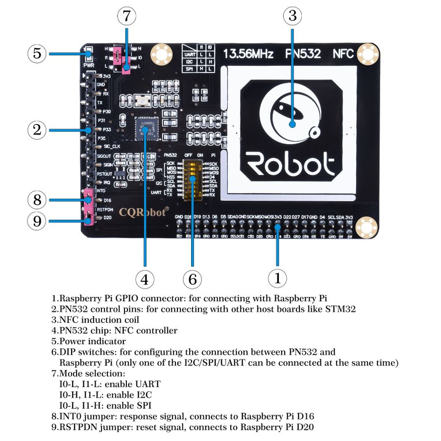
What's on Board
Testing by PC
You can quick test the module by connecting it to PC with USB to TTL module instead of Raspberry Pi
1. Hardware connection
| PN532 NFC HAT | USB to TTL Module |
|---|---|
| 3V3 | 3.3V |
| GND | GND |
| TX | RX |
| RX | TX |
2. Set L0 to L and L1 to L by jumpers
3. Connect USB to TTL Module to PC by USB cable
4. Open Serial assistant software, set it
| Key | Value |
|---|---|
| Baud rate | 115200 |
| Data bits | 8 |
| Stop bits | 1 |
| Parity | None |
| Flow control | None |
5. Check "HEX SEND" and "HEX SHOW"
6. Select correct serial port and open
7. Send data below to wake up FN532 module:
55 55 00 00 00 00 00 00 00 00 00 00 00 00 00 00 FF 03 FD D4 14 01 17 00
(Please refer to PN532 User Manual HSU wake up condition Chapter)
The response from PN532 module should be:
00 00 FF 00 FF 00 00 00 FF 02 FE D5 15 16 00
8. Send data below to scan Mifare Classic card(The blue card provided, hereafter called as "card")
00 00 FF 04 FC D4 4A 01 00 E1 00
Closing card to coil part of module, module scan it and response:
00 00 FF 0C F4 D5 4B 01 01 00 04 08 04 XXXXXXXXXX 00
XXXXXXXXXX in response data is ID (3 bytes) and checksum (1 byte) of card.(Please refer to PN532 User Manual InListPassiveTarget Chapter)
Demos
PN532 NFC HAT supports UART, I2C and SPI interface. You can use them according to your situation.After connecting PN532 NFC HAT (hereafter called as PN532) to Raspberry PI, then set the L1, L0 jumpers and DIP switch for different interfaces.
Choose the interface:
- UART: By default, UART interface of Raspberry Pi is used for Sheell debugging. If you use serial port for degbugging, you need to add an USB to TTL module for communicating just like what we do on #Testing by PC. In this case, the serial port is mapped as ttyUSB0 instead of ttyS0
- I2C: Raspberry Pi doesn't supports I2C Clock Stretching. However, PN532 may use Clock Stretching (slaver pull-down SCL pin of I2C interface). Clock Stretching cause that Raspberry Pi cannot control all I2C devices, therefore, if you need to connect other i2C device, we do not recommend you to use I2C interface.
- SPI: We use D4 (BCM) pin as Chip select pin of SPI interface. Take care about GPIO conflict.
Raspberry Pi
Download demo code from #Resources, unzip and copy raspberrypi folder to /home/pi of Raspberry Pi. You can firstly copy it to /boot of SD card, then copy it to /home/pi.
SPI Interface
1. Set L0 toL and L1 to H by jumpers
2. Connect RSTPDN->D20 by jumper
3. Set DIP switch to
| SCK | MISO | MOSI | NSS | SCL | SDA | RX | TX |
|---|---|---|---|---|---|---|---|
| ON | ON | ON | ON | OFF | OFF | OFF | OFF |
4. Connect PN532 NFC HAT to Raspberry Pi
Connect PN532 NFC HAT to Raspberry Pi via SPI interface
| PN532 NFC HAT | Raspberry Pi (BCM) |
|---|---|
| SCK | SCK |
| MISO | MISO |
| MOSI | MOSI |
| NSS | P4 (D4) |
5. Enable SPI interface
Open Terminal of Raspberry Pi,use command: sudo raspi-config
Choose Interfacing Options -> SPI -> Yes
6. Run demo codes(Use example_get_uid.py and rpi_get_uid.c as example)
Open Terminal, navigate to directory of demo codes
cd ~/raspberrypi/
1) python code:
Enter directory of python codes:
cd ~/raspberrypi/python/
Modify example_get_uid.py file,set the initialize code as:
pn532 = PN532_SPI(debug=False, reset=20, cs=4)
#pn532 = PN532_I2C(debug=False, reset=20, req=16)
#pn532 = PN532_UART(debug=False, reset=20)
Save after modifying, then run the codes with command:
python3 example_get_uid.py
2) C codes:
Enter directory of c code: cd ~/raspberrypi/c/example/
Modify rpi_get_uid.c file, set initialize code as:
PN532_SPI_Init(&pn532);
//PN532_I2C_Init(&pn532);
//PN532_UART_Init(&pn532);
Save and compile:sudo make
Run the code:
./rpi_get_uid.exe
7. Expected result:Close card to coil part of PN532, the UID of card is read
UART interface
1. Set L0 to L and L1 to L by jumpers
2. Connecting RSTPDN ->D20 by jumper
3. Set DIP switch to
| SCK | MISO | MOSI | NSS | SCL | SDA | RX | TX |
|---|---|---|---|---|---|---|---|
| OFF | OFF | OFF | OFF | OFF | OFF | ON | ON |
PN532 NFC HAT-3.jpg 4. Connect PN532 to Raspberry Pi
Connect PN532 NFC HAT to Raspberry Pi via UART interface
| PN532 NFC HAT | Raspberry Pi |
|---|---|
| RX | TX |
| TX | RX |
5. Enable Serial port. By default, serial port is used for Shell debugging.
Open Terminal of Raspberry PI and run command: sudo raspi-config
Choose Interfacing Options-> Serial -> No -> Yes
【Note】You need to restart Raspberry Pi after enabling serial port
6. Run demo codes(Use example_get_uid.py and rpi_get_uid.c as examples)
Open Terminal and navigate to directory of demo codes:
cd ~/raspberrypi/
1) python code:
Enter directory of python code:
cd ~/raspberrypi/python/
Modify example_get_uid.py file, set initialize code to:
#pn532 = PN532_SPI(debug=False, reset=20, cs=4)
#pn532 = PN532_I2C(debug=False, reset=20, req=16)
pn532 = PN532_UART(debug=False, reset=20)
Save.Then run code by command:
python3 example_get_uid.py 2) C code:
Enter directory of c code:
cd ~/raspberrypi/c/example/
Modify rpi_get_uid.c file, set initialize code to:
//PN532_SPI_Init(&pn532);
//PN532_I2C_Init(&pn532);
PN532_UART_Init(&pn532);
Save then compile code: sudo make
Run code:
./rpi_get_uid.exe
7. Expected result:Close card to coil part of PN532, the UID of card is read
If demo code of UART run failed, you can test serial port by this example cd ~/raspberrypi/python/ python3 example_uart_hex.py Enter data and sent, data sent and received should be printed on terminal as expected. e.g. sent data below to wake up PN532:
55 55 00 00 00 00 00 00 00 00 00 00 00 00 00 00 FF 03 FD D4 14 01 17 00
The response data should be:
00 00 FF 00 FF 00 00 00 FF 02 FE D5 15 16 00
I2C interface
1. Set K0 as H, L1 as L by jumpers
2. Connect RSTPDN ->D20 and INT0 -> D16(avoid from Clock Stretching) by jumpers
3. Set DIP switch to
| SCK | MISO | MOSI | NSS | SCL | SDA | RX | TX |
|---|---|---|---|---|---|---|---|
| OFF | OFF | OFF | OFF | ON | ON | OFF | OFF |
PN532 NFC HAT-3.jpg 4. Connect PN532 to Raspberry Pi
Connect PN532 NFC HAT to Raspberry Pi via I2C interface
| PN532 NFC HAT | Raspberry Pi |
|---|---|
| SCL | SCL |
| SDA | SDA |
5. Enable I2C interface
Open Terminal of Raspberry Pi and run command: sudo raspi-config
Choose Interfacing Options-> I2C -> Yes
6. Run code(Use example_get_uid.py and rpi_get_uid.c as examples)
Open ternimal and navigate to directory of demo codes:
cd ~/raspberrypi/
1) python code:
Enter directory of python code: cd ~/raspberrypi/python/
Modify example_get_uid.py file, set initialize code to:
#pn532 = PN532_SPI(debug=False, reset=20, cs=4)
pn532 = PN532_I2C(debug=False, reset=20, req=16)
#pn532 = PN532_UART(debug=False, reset=20)
Save, then run code
python3 example_get_uid.py 2) C code:
Enter directory of c code:cd ~/raspberrypi/c/example/
Modify rpi_get_uid.c file, set initialize code to:
//PN532_SPI_Init(&pn532);
PN532_I2C_Init(&pn532);
//PN532_UART_Init(&pn532);
Save then compile codes:sudo make
Run code:
./rpi_get_uid.exe
7. Expected result:Close card to coil part of PN532, the UID of card is read


