Difference between revisions of "Serial Data Logger SKU: PZSSD002"
(→Example and Test Code) |
(→Example and Test Code) |
||
| Line 105: | Line 105: | ||
[[File:PZSSD003-4.jpg|600px]] | [[File:PZSSD003-4.jpg|600px]] | ||
| + | |||
| + | '''2.2 Serial port to send data''' | ||
| + | |||
| + | Enter the Raspberry Pi terminal, execute the following command to open the serial port software | ||
| + | |||
| + | <pre> | ||
| + | sudo apt-get install minicom | ||
| + | sudo minicom -D /dev/ttyS0 | ||
| + | </pre> | ||
| + | |||
| + | [[File:PZSSD003-5.jpg|600px]] | ||
| + | |||
| + | Press Ctrl+A--->Z--->E key | ||
| + | |||
| + | [[File:PZSSD003-6.jpg|600px]] | ||
| + | |||
---- | ---- | ||
Revision as of 12:16, 15 January 2023
Contents
Introduction
Compared to the previous MicroSD Card Module, this Pzsmocn serial data logger V1 can store data more conveniently, and supports direct data printing through serial port without additional codes.
The Pzsmocn serial data logger V1 supports 32GB TF card, Onboard high-performance AC6925B chip, making it suitable for long-time data storage. It comes with a USB function, which means you can directly connect it to a PC to read the stored files without using a card reader. Meanwhile, with the onboard LED indicator, data writing status can be viewed visually. And the onboard SAVE pin makes it easier to store data into separate files.
AC6925B Chip Specification Download
Media: AC6925B Datasheet V1.0.pdf
Application
- Offline Data Collection
- Capture Product Debug Logs
- Robots and Drones Debug
Product Display
Specifications
- Model: PZSSD002
- Main Chip: AC6925B
- Supply Voltage: 3.3V to 5V
- Operating Current: 23mA
- USB Protocol: USB2.0
- Operating Temperature Range: -30 Degree Celsius to +85 Degree Celsius
- Operating Humidity Range: 5%RH to 85%RH
- Support: 32GB TF card
- Dimension: 23.5mm * 25mm
- Mounting Hole Size: 3.0mm
Pin Description
Note: The SD LED indicator is an indicator for data interaction between the module and the storage, and the light flashes when data is written or a new file is created.
First Time Using
- If the storage is not formatted, please format the storage first, the file system is FAT32.
- Power on the module for more than 2S (non-USB host), so that the module will automatically generate the CONFIG.TXT file, and the SD light will flash once.
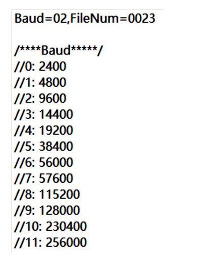
- Check whether the CONFIG.TXT file is generated normally. You can modify the communication baud rate and file storage name of the module by modifying CONFIG.TXT.
- Baud: Serial communication baud rate selection (00 corresponds to 2400 baud rate, 01 corresponds to 4800 baud rate), the module baud rate matches the main control serial port printing baud rate to store data normally.
- FIleNum: The file serial number of the next new file (FileNum=0099, the next generated file name is FILE0099.txt), if the file already exists, it will skip this file and continue to search.
Notice
- Do not send data to the serial port of the module before the CONFIG.TXT file is generated.
- Do not connect USB and serial port at the same time.
- Connect to the computer via USB, it is recommended to eject the U disk and then pull out the module.
Example and Test Code
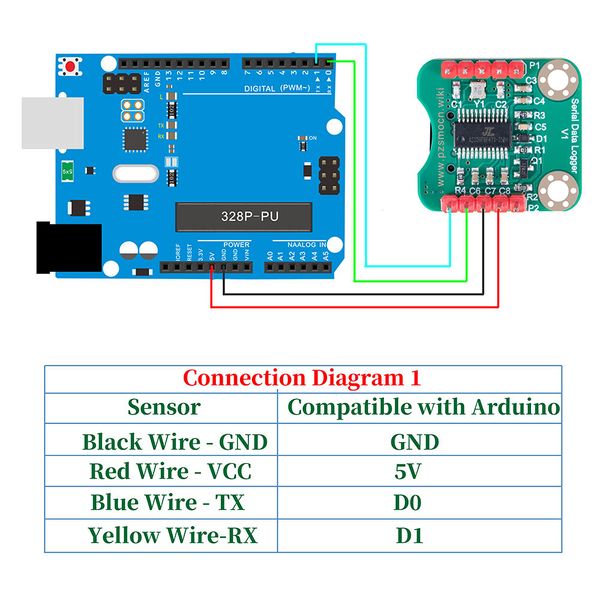
1. Arduino Connection Method
Note: The DuPont wire female single-head wiring we distribute cannot be directly connected to the UNO R3 control board. When wiring, it is necessary to stack the sensor expansion board on the UNO R3 control board, or connect the male-to-male Dupont wire (bread wire) on the Dupont wire female single-head wiring.
In the experiment, we connected the interface of the sensor to the UNO R3 control board.
1.1 Download and Run the Test Examples
Media: PZSSD002_Arduino_Code_A.rar
1.2 Arduino test code
#define SPIN 6  //Connect the S pin of the module, and the low level triggers to save the file.
uint16_t i = 0;
void setup(void){
  Serial.begin(9600);
  delay(2000);  //To prevent data loss, delay for a period of time and wait for the module to start.
  pinMode(SPIN, OUTPUT);
  digitalWrite(SPIN, HIGH);}
void loop(void){
  Serial.println(String(i));
  i++;
  if((i % 10) == 0){
    digitalWrite(SPIN, LOW);
    delay(500);
    digitalWrite(SPIN, HIGH);
  }
  delay(300);
  }
1.3 Test methods and results
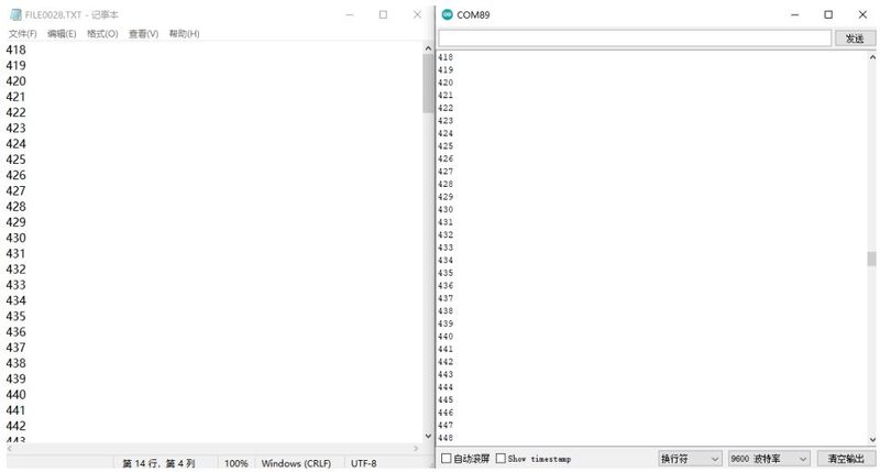
Upload the program to the Arduino control board, first connect VCC and GND, then the S LED light of the module will flash once; Save the data once; insert the SD into the computer and open the text under the FILE file to see the saved data.
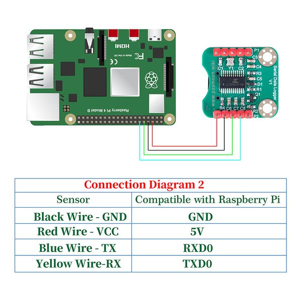
2. Raspberry Pi Connection Method
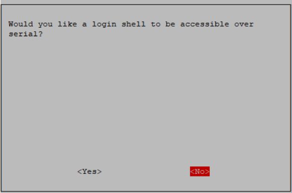
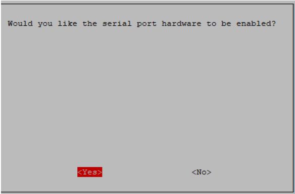
2.1 Initialize the UART first, and enter the command sudo raspi-config----->3 Interface Options---->I6 serial Port--->No---->Yes---->Finish in the terminal
2.2 Serial port to send data
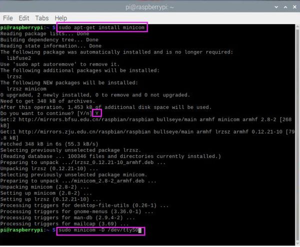
Enter the Raspberry Pi terminal, execute the following command to open the serial port software
sudo apt-get install minicom
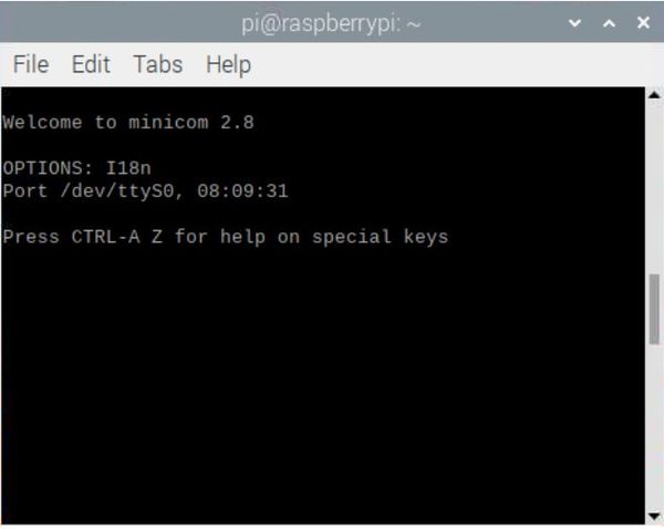
sudo minicom -D /dev/ttyS0
Press Ctrl+A--->Z--->E key


