Difference between revisions of "Hall Sensor SKU: PZSHED0001"
(→Case and Test Code) |
(→Case and Test Code) |
||
| (15 intermediate revisions by the same user not shown) | |||
| Line 15: | Line 15: | ||
|[[File:PZSHED0001-2.jpg |left|400px]] | |[[File:PZSHED0001-2.jpg |left|400px]] | ||
|} | |} | ||
| + | ---- | ||
| + | =='''DataSheet '''== | ||
| + | [[Media: OH9249.pdf]] | ||
---- | ---- | ||
| Line 20: | Line 23: | ||
'''Arduino Connection Method''' | '''Arduino Connection Method''' | ||
{|- | {|- | ||
| − | |[[File:PZSHED0001-3.jpg |left| | + | |[[File:PZSHED0001-3.jpg |left|600px]] |
|} | |} | ||
| + | '''Arduino Code''' | ||
| + | <pre> | ||
| + | int ledPin = 13; // choose the pin for the LED | ||
| + | int inputPin = 2; // Connect Hall sensor to Pin2 | ||
| + | int val = 0; // variable for reading the pin status | ||
| + | void setup() { | ||
| + | pinMode(ledPin, OUTPUT); // declare LED as output | ||
| + | pinMode(inputPin, INPUT); // declare pushbutton as input | ||
| + | } | ||
| + | void loop(){ | ||
| + | val = digitalRead(inputPin); // read input value | ||
| + | if (val == HIGH) { // check if the input is HIGH | ||
| + | digitalWrite(ledPin, LOW); // turn LED OFF | ||
| + | } else { | ||
| + | digitalWrite(ledPin, HIGH); // turn LED ON | ||
| + | } | ||
| + | } | ||
| + | </pre> | ||
| + | [[Media: Hall Magnetic Sensor - Arduino Code Download.rar]] | ||
| + | |||
| + | |||
| + | |||
| + | |||
| + | '''Test Result''': According to the wiring diagram, the Arduino uploads the code, and after power-on, when we use a magnet to approach the digital Hall magnetic sensor, we will find that the small light is on. When we remove the magnet, the LED turns off. | ||
| + | ---- | ||
| + | '''Raspberry Pi Connection Method''' | ||
| + | {|- | ||
| + | |[[File:PZSHED0001-4.jpg |left|600px]] | ||
| + | |} | ||
| + | '''Raspberry Pi Test Method''' | ||
| + | *Connect the sensor to the Raspberry Pi 4B, and put the test code on the Raspberry Pi system in the form of a folder. | ||
| + | *If pip is not installed, you must install pip first: (skip this step if installed) | ||
| + | *Enter the code file on the left side of the Raspberry Pi, right-click and select Open with... | ||
| + | {|- | ||
| + | |[[File:PZSHED0001-8.jpg |left|600px]] | ||
| + | |} | ||
| + | Choose '''Geany''' Software | ||
| + | {|- | ||
| + | |[[File:PZSHED0001-9.jpg |left|600px]] | ||
| + | |[[File:PZSHED0001-10.jpg |left|600px]] | ||
| + | |} | ||
| + | '''Raspberry Pi Code''' | ||
| + | <pre> | ||
| + | import RPi.GPIO as GPIO | ||
| + | from time import sleep | ||
| + | val=0 | ||
| + | |||
| + | sensorPin = 18 | ||
| + | |||
| + | |||
| + | GPIO.setmode(GPIO.BCM) | ||
| + | |||
| + | GPIO.setup(sensorPin,GPIO.IN) | ||
| + | |||
| + | while True: | ||
| + | val = GPIO.input(sensorPin) | ||
| + | print(val); | ||
| + | if(val == 0): | ||
| + | print("No induction") | ||
| + | else: | ||
| + | print("A magnetic field") | ||
| + | sleep(0.1) | ||
| + | GPIO.cleanup() # Release all GPIO | ||
| + | </pre> | ||
| + | [[Media: Hall Magnetic Sensor - Raspberry Pi Code Download.rar]] | ||
---- | ---- | ||
Latest revision as of 06:34, 13 January 2022
Description
The magnetic sensor based on the Hall induction principle can be used to detect magnetic materials (magnets), regardless of polarity, and the range can reach about 3cm (the detection range is related to the strength of magnetism). It has the advantages of being sensitive to magnetic field, simple structure, small size, wide frequency response, large output voltage change and long service life.
Note:It's a omnipolar magnet dectector so that it can not tell two polarities apart.
Specifications
- Working Voltage: 3.3V to 5V
- Output Signal: usually output low level, output high level when magnetism is detected (at the same time the onboard LED is on)
- Product Size: 30mm * 22.0mm
- Fixing Hole Size: 3mm
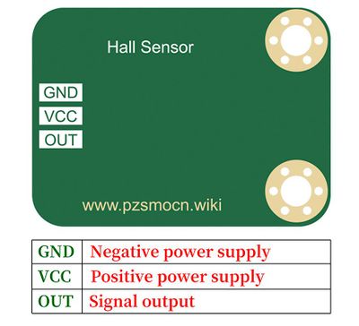
Pin Description
DataSheet
Case and Test Code
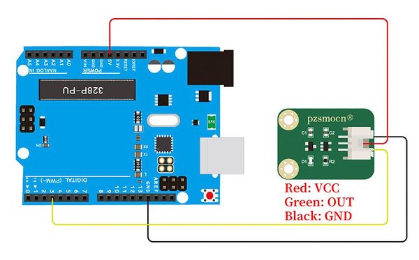
Arduino Connection Method
Arduino Code
int ledPin = 13;                // choose the pin for the LED
int inputPin = 2;               // Connect Hall sensor to Pin2
int val = 0;                    // variable for reading the pin status
void setup() {
  pinMode(ledPin, OUTPUT);      // declare LED as output
  pinMode(inputPin, INPUT);     // declare pushbutton as input
}
void loop(){
  val = digitalRead(inputPin);  // read input value
  if (val == HIGH) {            // check if the input is HIGH
    digitalWrite(ledPin, LOW);  // turn LED OFF
  } else {
    digitalWrite(ledPin, HIGH); // turn LED ON
  }
}
Media: Hall Magnetic Sensor - Arduino Code Download.rar
Test Result: According to the wiring diagram, the Arduino uploads the code, and after power-on, when we use a magnet to approach the digital Hall magnetic sensor, we will find that the small light is on. When we remove the magnet, the LED turns off.
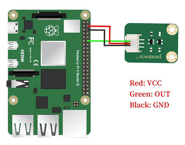
Raspberry Pi Connection Method
Raspberry Pi Test Method
- Connect the sensor to the Raspberry Pi 4B, and put the test code on the Raspberry Pi system in the form of a folder.
- If pip is not installed, you must install pip first: (skip this step if installed)
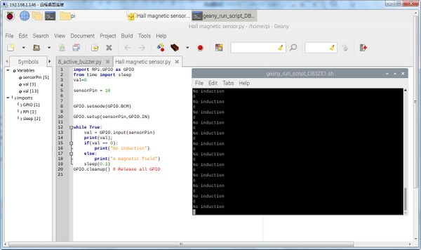
- Enter the code file on the left side of the Raspberry Pi, right-click and select Open with...
Choose Geany Software
Raspberry Pi Code
import RPi.GPIO as GPIO
from time import sleep
val=0

sensorPin = 18


GPIO.setmode(GPIO.BCM)

GPIO.setup(sensorPin,GPIO.IN)

while True:
    val = GPIO.input(sensorPin)
    print(val);
    if(val == 0):
        print("No induction")
    else:
        print("A magnetic field")
    sleep(0.1)
GPIO.cleanup() # Release all GPIO
Media: Hall Magnetic Sensor - Raspberry Pi Code Download.rar

